Chemical Dosing
Purpose and Description
The coagulation and disinfection processes require the precise dosage of coagulant to the plant influent and calcium hypochlorite to the plant effluent. To carry out this process without pumps, the AguaClara plant uses a hydraulic dosing system.
The main components of the system are:
Tanks to store the coagulant and chlorine stock solutions
An elevated platform to support the chemical storage tanks at the correct elevation for gravity powered dosing
A flow measurement calibration column for each chemical
A pair of constant level tank with float valves that maintains a constant level for both chemical solutions
Two dosing tube modules that provide the necessary relationship between pressure drop and chemical flow rates for each chemical
A chemical doser (the balance) that connects the water level in the plant’s entrance tank to the level at the outlet of the chemical dosing system
This system has the characteristic of maintaining a constant chemical dosage even as the flow rate through the plant varies. The plant operator can vary the chemical dosage directly, without doing any calculations, and without having to manipulate the system every time the flow rate in the plant changes. The AguaClara dosing system provides the added benefit of automatically turning off the chemical flow when there is no flow in the plant. This provides security against contamination with excess chemicals and chemical waste in the event that the plant is shut down inadvertently as may occur if the transmission line is damaged.
General Specifications
Parameter |
value |
|---|---|
Plant maximum flow rate |
12 L/s |
Maximum head loss thru doser tubes |
200 mm |
Coagulant stock concentration |
120 g/L |
Coagulant maximum dose |
50 mg/L |
Coagulant maximum flow rate |
5 mL/s |
Chlorine stock concentration |
8 g/L |
Chlorine maximum dose |
2 mg/L |
Chlorine maximum flow rate |
3 mL/s |
The constant level tank system provides convenient central controls for selection of stock tank, flow calibration, purging sediment, and selection of which of the duplicate chemical feed systems to use. The system has built in redundancy with duplicate systems for dosing each chemical to facilitate routine cleaning and maintenance.
Constant Level Tanks
The dosing system controls are centralized around the constant level tanks (see Fig. 5).
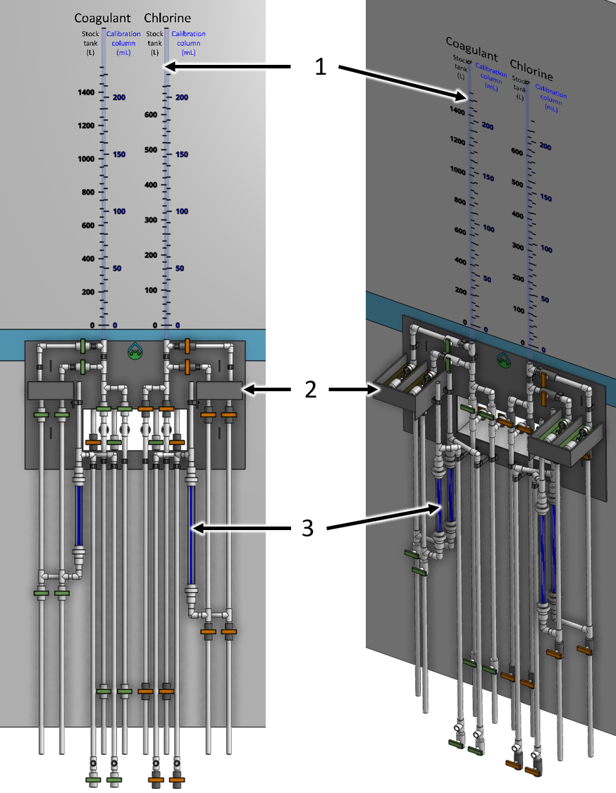
Fig. 5 Overview of the constant level tank module mounted on the side of the chemical stock tank platform.
Key |
Description |
|---|---|
1 |
chlorine stock tank volume and flow calibration column sight tube |
2 |
constant level tank |
3 |
dosing tube module |
The constant level tanks prevent the changing chemical levels in the stock tanks from influencing the flow rate thru the dosing system. Float valves maintain a relatively constant level of chlorine and coagulant. The float valves are sized to provide up to the maximum chemical flow rate of 5 mL/s given the minimum head provided by stock tanks (300 mm).

Fig. 6 Constant level tank with associated valves and dosing tubes. The valves with orange handles are compatible with chlorine and have chlorine resistant o’rings.
Key |
Description |
|---|---|
1 |
coagulant stock tank volume and flow calibration column sight tube |
2 |
valve to select constant level tank and dosing tube set |
3 |
float valve to provide constant level of coagulant |
4 |
constant level tank |
5 |
air vent to discharge bubbles from dosing tubes |
6 |
valve to select which stock tank to use |
7 |
dosing tubes to provide linear relationship between chemical flow rate and head loss |
8 |
valve to drain constant level tank (for cleaning with vinegar) |
9 |
sediment trap to capture particles from the stock tank |
10 |
valve to purge the sediment trap |
11 |
connection to feed line to the doser |
12 |
valve to drain the line going to the doser (for cleaning with vinegar) |
There is a pair of constant level tanks for each chemical feed. The specifications for each tank is given in Table 6.
Parameter |
value |
|---|---|
Minimum head provided by stock tanks |
300 mm |
Maximum head loss through the float valve orifice |
167 mm |
Float valve orifice diameter |
2.36 mm |
Tank inner length |
258 mm |
Tank inner width |
100 mm |
Tank depth |
79.1 mm |
Tank fluid depth |
29.1 mm |
Dosing Tubes
Dosing tubes use laminar flow in a long straight small diameter tube to establish a linear relationship between head loss and flow rate. The velocity in the tubes is limited to ensure that minor losses that scale with velocity squared remain less than 0.05 of the maximum head loss, 200 mm, is from minor losses.
The number of dosing tubes is increased as needed to ensure that the maximum allowable tube velocity is not exceeded. The dosing tubes are mounted in a module

Fig. 7 The dosing tubes are assembled in a module to facilitate cleaning and replacement.
Key |
Description |
|---|---|
1 |
reducer |
2 |
union |
3 |
part of union that is glued to the pipe shield and disk |
4 |
dosing tubes |
5 |
pipe shield that maintains the dosing tubes in tension |
6 |
PVC disk that is glued to the union and that has slightly undersized holes for the dosing tubes |
7 |
isometric view of the union showing that the dosing tubes are visible above the disk |
The coagulant dosing tube specifications are given below.
Parameter |
value |
|---|---|
Number of tubes per module |
3 |
Tube inner diameter |
3.18 mm |
Tube outer diameter |
6.35 mm |
Tube length |
2.37 m |
Pipe guard length |
2.29 m |
The chlorine dosing tube specifications are given below.
Parameter |
value |
|---|---|
Number of tubes per module |
5 |
Tube inner diameter |
1.59 mm |
Tube outer diameter |
4.76 mm |
Tube length |
484 mm |
Pipe guard length |
418 mm |
Doser
Pending.
Injection Points
Pending.